Points
Overview#
A point in this context refers to a 2D point [x,y] with a rotation/orientation r and some extra metadata added in.
These can be thought of as the middle points of the keycaps in a resulting keyboard layout, with the additional handling of the angle of the keycap, plus, again, some metadata (like names, row/column information, custom variables, etc.).
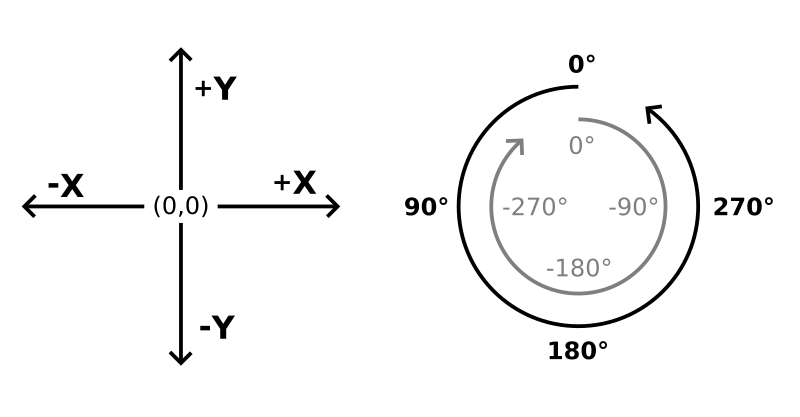
The basic coordinate system works just like your math workbooks did: X values are positive to the right, negative to the left, while Y values are positive upward, negative downward.
Additionally, rotation represents the direction of the Y axis, and changes to it work counter-clockwise (so +90° turns to the left, while -90° turns to the right).
Throughout this doc, we'll often reference points in the form [x, y, r°].
Points are an important part of keyboard creation as they can later be used to position shapes (to form board outlines) and PCB footprints – optionally by using filters to use only a subset. But thing would get pretty tedious if we had to lay out each point manually, and downright horrific if any kind of trigonometry came into play! So Ergogen tries to do as much of the heavy lifting as it can while providing more comfortable declaration alternatives.
Anchors#
One of these alternatives is the use of anchors, where we don't directly specify a point's x/y/r coordinates, but compute them from an already existing starting point through some translation/rotation/adjustment.
Of course, direct point declarations are also possible when starting from [0, 0, 0°] and translating/rotating right to where you want the point to be, but we can do better than that.
Anchors try to be very flexible, and it naturally comes with some complexity – but remember that they are just another way to declare a point.
Anchors can be parsed from the following data types:
A string means it's just a reference to an already existing point with that name, without any further modifications.
An array means it's a multipart anchor (or, multi-anchor), each item being an anchor itself, recursively. But why would we need multiple anchors for a single point, you might ask. Because each sub-anchor becomes the starting point of the next.
tip
Think of this as a kind of treasure hunt where you first have to find a clue to know where the next clue will be. Through this follow-the-dots functionality, you can get to many interesting, exact locations on your board without having to actually calculate where that is.
An object means it's a full anchor declaration.
Attributes#
In a full, object anchor declaration, the following fields can be used:
refis the starting point from where the anchor will perform its additional modifications. This field is parsed as an anchor itself, recursively. So in its easiest form, it can be a string to designate an existing starting point by name (more on names later), but it can also be a full nested anchor if so desired.aggregateis an alternative torefwhen the combination of several locations is required as the starting point for further adjustment. They're mutually exclusive, so we can use eitherreforaggregatein any given anchor. The aggregate field is always an object, containing:- a
partsarray containing the sub-anchors we want to aggregate, and - a
methodstring to indicate how we want to aggregate them.
The only method implemented so far is
average, which is the default anyway, so themethodcan be omitted for now.note
Averaging applies to both the
x/ycoordinates and therrotation.- a
orientis a kind of pre-rotation, meaning it happens before any shifting is done. The value can be:- a number, in which case that number is simply added to the current rotation of the in-progress point calculation; or
- a sub-anchor, in which case the point "turns towards" the point we reference (meaning its rotations will be exactly set to hit that point if a line was projected from it).
note
Orienting only affects the
rvalue of the point we're calculating.shiftis for shifting (or, more formally, translating) the point on the XY plane. The value can be:- a array of exactly two numbers, specifying the
xandyshift, respectively, or - a single number, which would get parsed as
[number, number].
caution
It's important that shifting happens according to the current rotation of the point. By default, a 0° rotation is "looking up", so that positive
xshifts move it to the right, negativexshifts to the left, positiveyshifts up, negativeyshifts down. But if r=90° (so the point is "looking left", as, remember, rotation works counter-clockwise), then a positivexshift would move it upward.- a array of exactly two numbers, specifying the
rotateis a kind of post-rotation after shifting, as opposed to howorientwas the pre-rotation. Otherwise, it works the exact same way.affectcan specify an override to what fields we want to affect during the current anchor calculation. The value can be:- a string containing a subset of the characters
x,y, orronly; or - an array containing a subset of the one letter strings
"x","y", or"r"only.
tip
Let's say you have a point rotated 45° and want to shift is "visually right". You could either reset its rotation via
orient, then shift, then reset the rotation withrotate; or, you could do the shift and then declare that this whole anchor onlyaffects"x". The amount of shifting wouldn't be the same, but the important thing is that you could constrain the movement to the X axis this way.Or let's say you want to copy the rotation of another, already existing point into your current anchor calculation. You can do so using a multi-anchor (see above),
referencing the existing point in the second part, and then declareaffect: "r"to prevent it from overwriting anything else, thereby setting just the rotation.- a string containing a subset of the characters
resiststates that we do not want the special treatment usually afforded to mirrored points. We'll get to mirroring in a second, but from an anchor perspective, all we need to know is that shifting and orienting/rotating are all mirrored for mirrored points, to keep things symmetric. So if we specify a shift of[1, 1]on a mirrored point, what actually gets applied is[-1, 1], and rotations are clockwise (read, counter-counter-clockwise) in those cases, too. But if we don't want this behavior, (say, because PCB footprints go on the same, upward facing side of the board, no matter the half) we canresistthe special treatment.
Examples#
Basic
To get the gist of what's happening, take a look at the following anchor config and its visualization. It first orients itself 45°, then it shift "one to the right", but since its orientation is now 45°, "right" means "up and to the right" along the diagonal line. Once it gets there (at [√2/2, √2/2], on the unit circle), it finally rotates another 135°, which (when added to its existing rotation) results is 180°, so it's looking "down".
- Config
- Visualization
anchor: orient: 45 shift: [1, 0] rotate: 135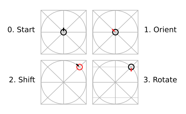
Follow-the-dots
We can now turn towards multi-anchors, which are just regular anchors in an array.
Arrays in YAML are denoted by using the dash (-) notation and an extra level of indent.
The first item is the same as above, meaning we're starting from the same situation as the basic example.
Only now, the result of the basic example won't be the end, only the starting point of a second anchor component.
Shifting with a positive x coordinate usually means "visually right", but remember that our starting point (resulting from the first sub-anchor) faces down, so positive x values here mean "visually left".
On top of this, we demonstrate how rotate (or orient) works when given a sub-anchor instead of a number, turning towards the center, automatically calculating the degrees of rotation it requires.
Hopefully this demonstrates how easy it is to get to very non-obvious coordinates using nice "round" numbers only – no π in sight!
For the record, the final result is a point at [-0.293, 0.707, -157.5°].
- Config
- Visualization
anchor: - orient: 45 shift: [1, 0] rotate: 135 - shift: [1, 0] rotate.shift: [0, 0]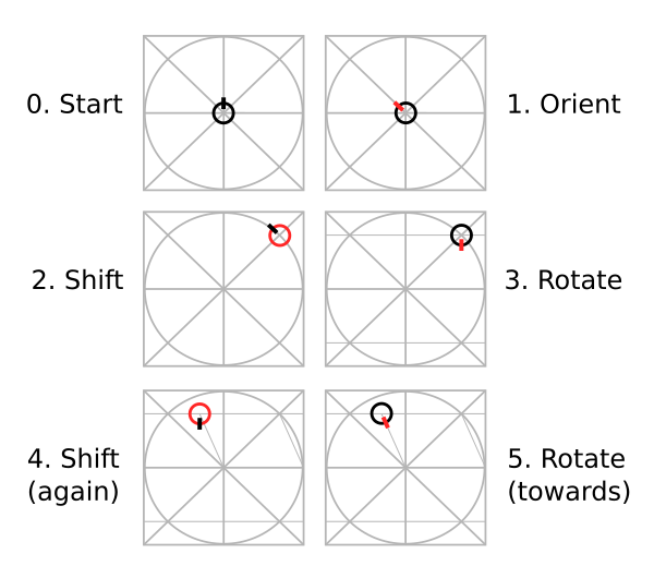
Averaging
Here we can see how to aggregate two existing points.
left is at [-1, 0, -90°], marked green, while right is at [1, 0, 90°], marked blue.
Aggregating without a method defaults to average, so what we get as our aggregated point is the good 'ol [0, 0, 0°] that we would have started with anyway.
Note that the rotation also got averaged, not just the x/y coordinates.
From here on out, it's the same as if we referenced a single existing starting point, or left it empty for the default [0, 0, 0°].
We can perform any additional shifting or rotating, make this a part of a multi-anchor, whatever...
- Config
- Visualization
anchor: aggregate.parts: - left - right shift: [1, 0] rotate: 180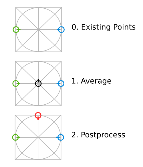
Affecting
Let's say we have an existing point at [-1, 0, 45°], fittingly named existing, and we want a new point "facing the other way".
It would be easy to add 180° to its rotation, if we knew it – but as we saw in previous examples, some coordinate values are not exactly round numbers and using them would be easier through calculation.
Fortunately, we don't have to recalculate it, either.
We can just reference the existing point, and then pick-and-choose what we want to reuse from it using affect.
So we get a multi-anchor going by first shifting our point to where we want it to be on the x/y plane, then adding a second part that refs the existing point and make some further adjustments.
Normally, specifying a ref would overwrite all progress we've made so far, but affect to the rescue.
- Config
- Visualization
anchor: - shift: [0, 1] - ref: existing rotate: 180 affect: r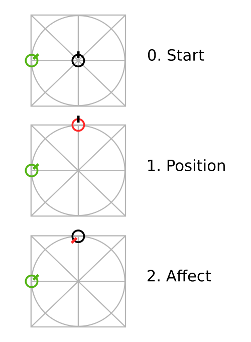
Resisting
Let's take the same starting point we have in the Averaging example, only now the existing points are not separate, but mirror images of each other, named left at [-1,0,-90°] (green) and mirror_left at [1,0,90°] (blue).
Read more on mirroring later.
So, if we do an ordinary right shift and some counter-clockwise (positive) rotation on a "normal" point, we get the normal result.
Remember, though, that since left is facing towards the middle, a "rightward" shift from its perspective is going to be moving "visually down" (see 1).
Now the interesting part: when we do the same "rightward" shift + positive rotation on a mirrored point, what actually happens is a seemingly leftward shift and a negative rotation, to keep the mirror image in sync with its source (see 2).
If we don't want this, we can specify the same with an additional resist: true and now the mirrored point will also do a rightward shift (from its perspective!) and counter-clockwise rotation (see 3).
- Config
- Visualization
# 1, default non-mirrored caseanchor_1:  ref: left  shift: [1, 0]  rotate: 45
# 2, default mirrored caseanchor_2:  ref: left_mirror  shift: [1, 0]  rotate: 45
# 3, mirrored case with resistanceanchor_3:  ref: left_mirror  shift: [1, 0]  rotate: 45  resist: true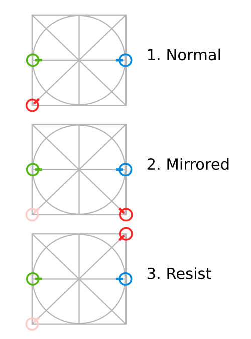
Zones#
Anchors are a great way to dial in the exact position of a single point, but they would be cumbersome for whole keyboards.
So while you'll be using anchors all the time in sub-fields of your config, the main approach to define batches of points is through the use of zones.
Basics#
I'm probably not revealing a big secret if I confess that "Ergogen" is just a contraction of "Ergonomic Generator". And what makes it "Ergo" is its opinionated, explicit focus on the column-stagger. This means that instead of the more common rows-then-columns order, Ergogen lays out zones columns first, left-to-right by default. A collection of columns comprises a zone, and we can have as many zones as we'd like – for example, to differentiate the keywell and the thumb fan/cluster. Columns can be staggered and splayed relative to each other, while zones can be anchored to each other so that everything is right where you want it. Within columns, the rows are built from bottom to top by default.
A full zone declaration looks something like this (in the context of the whole config):
points: zones: <zone_name>: # A unique key for each zone anchor: # Optional anchor to position the zone, default = [0, 0, 0°] columns: <column_name>: # A unique key for each column within the zone rows: <row_name>: <defs> # Key-level attributes set here apply to this key alone ... key: <defs> # Key-level attributes set here apply to the whole column ... rows: <row_name>: <defs> # Key-level attributes set here apply to the whole row ... key: <defs> # Key-level attributes set here apply to the whole zone ... key: <defs> # Key-level attributes set here apply to ALL zonesInheritance#
As you can see, there are quite a few places where these so-called key-level attributes can be defined. How are poor keys to know which to pay attention to, and which to ignore? Enter inheritance, where (somewhat similarly to the usual programming concept of inheritance) we go from generic to specific, override what we must, and just reuse the rest.
The inheritance order goes:
- Built-in, hardcoded defaults
- Global
points.keyoverrides - Zone-wide
points.zones.<zone_name>.keyoverrides - Column-wide
points.zones.<zone_name>.columns.<column_name>.keyoverrides - Row-wide
points.zones.<zone_name>.rows.<row_name>overrides - Key-specific
points.zones.<zone_name>.columns.<column_name>.rows.<row_name>overrides
All this complexity is only there to minimize the need for repetition. We can freely choose the best place for any key-level attribute where it can apply to all its victims while being declared only once. These sources "extend" each other in this order so by the time we reach a specific key, every level had an opportunity to modify something.
caution
As you might notice, levels 2-3-4 have a .key suffix while levels 5-6 do not!
This is because parent levels for the former three (points, points.zones.<zone_name> and points.zones.<zone_name>.columns.<column_name>, respectively) can have other content as well, while the latter two are exclusively for key-level attributes anyway.
note
The higher the number before an override, the higher chance it has to override anything that came before it. So values declared at the 6th, key-specific level are sacred and inviolable, while everything the user configures can override the lowly hardcoded defaults at level 1.
For example, let's suppose that a key-related attribute is already defined at the column-level (at points.zones.<zone_name>.columns.<column_name>.key, so level 4).
When we later encounter a key-level extension for this key (at points.zones.<zone_name>.columns.<column_name>.rows.<row_name>, so level 6) that specifies a few things but not this exact key, its value will stay the same instead of disappearing.
note
When we want it to disappear, UN-specifying values is also possible with the $unset directive, because this key-level inheritance relies on the same implementation we've discussed in the preprocessing section.
A common use-case for this is when you'd want to remove an additional pinky key.
You can still declare zone-wide bottom/home/top rows to apply to the ring/middle/index/inner columns, but for the pinky, you simply override as pinky.rows.top: $unset to be left with only two pinky keys.
When multiple levels define the same attribute and there is a "collision", simple values (like booleans, numbers, or strings) replace the old ones, while composites (arrays or objects) apply this same extension mechanism recursively, element-wise.
So when key = 1 is extended by key = 2, the result is key = 2.
But if key = {a: 1} is extended by key = {b: 2}, the result is key = {a: 1, b: 2}.
Lastly, if key = {a: 1} is extended by key = {a: $unset, b: 2}, the result is key = {b: 2}.
Keys#
Keys can contain any metadata as attributes (which may become useful later down the line), but only a handful has meaning when laying out positions. These are the following:
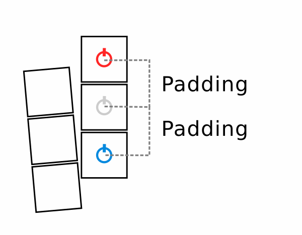
stagger: Column staggering means an extra vertical shift to the starting point of a whole column compared to the previous one (initially0, cumulative afterwards). Its default value is0(also overrideable with the$default_staggerinternal variable).spread: Once a column has been laid out,spread(the horizontal space between this column and the next) is applied before the layout of the next column begins. Its default value isu(also overrideable with the$default_spreadinternal variable).splay: As a kind of companion tospread,splayapplies a rotation (around an optionalorigin) to the starting point of a new column. Its default value is0(also overrideable with the$default_splayinternal variable), and it rotates around the default origin of[0, 0](meaning the center of where the first key in the column would go).padding: Once a point within a column is determined,paddingrepresents the vertical gap between it and the next row. Its default value isu(also overrideable with the$default_paddinginternal variable).orient/shift/rotate: The names might be familiar from the anchor section. And indeed, they do behave very similarly – only they are interpreted cumulatively within a column. The current keyorients(default =0),shifts(default =[0, 0]), and rotates (default =0), and in doing so, not only positions itself, but provides the starting point for the next row within the column (to which the abovepaddingcan be applied).adjust: This field is also used to adjust individual points – but, as opposed to the above trio, it's parsed as an actual anchor, and it applies independently, affecting only the current key and not the cumulative column layout.bind: Represents the amount of directional "reach" each key has when it tries to bind with its neighbors to form a contiguous shape. For a more in-depth explanation, check the outlines section. The value can be a number (uniform reach in every direction), an array of two numbers (horizontal/vertical reach), or an array of four numbers (top, right, bottom, and left reach, respectively – similarly to how CSS would assign things). The default is no bind (represented by-1, to differentiate from0length reaches).autobind: Enables automatically assigned binding in relevant direction to combine traditional keywells. For a more in-depth explanation, check the outlines section. Its default value is10(also overrideable with the$default_autobindinternal variable).skip: This field signals that the current point is just a "helper" and should not be included in the output. This can happen when a real point is more easily calculable through a "stepping stone", but then we don't actually want the stepping stone to be a key itself. The default is, of course,false.asym: Determines which side of the keyboard the key should belong to (see Mirroring). Its default value isboth.mirror: Provides a way to override any key-level attributes for mirrored keys (see Mirroring). Empty by default.colrow: Built-in convenience variable to store a concatenated name of the column and the row, uniquely identifying a key within a zone. Its value is{{col.name}}_{{row}}, built through templating (see below).name: The name of the key that identifies it uniquely not just within its zone, but globally. Its default value is{{zone.name}}_{{colrow}}, built through templating (see below).note
Single key zones are common helpers for defining and naming interesting points on the board. To spare you from having to reference these as
zonename_default_default(eachdefaultbeing the default column or row name, respectively, when nothing is specified),defaultsuffices are always trimmed. So for single key zones, the name of the key is equivalent to the name of the zone.width/height: Helper values to signify the keycap width/height intended for the current position(s).caution
These values only apply to the demo representation of the calculated key positions. For actual outlines to be cut (or used as a basis for cases), see the outlines section.
Other than these, any extra field can be specified, containing any value. These can become useful later when we want to pass key-specific information to PCB footprints (for example, which nets the current key should belong to).
Basic templating is supported to make reusing existing key-level attributes easier.
Anything within double curly braces ({{ and }}) inside a string is interpreted as a reference to, and is replaced by the key-level attribute of the same name.
This is how {{col.name}}_{{row}} automatically expands to something like pinky_home in the case of colrow, or how {{zone.name}}_{{colrow}} expands to something like keywell_pinky_home in the case of name.
For example, a simple one point config (1) creates the following internal representation with all key-level attributes filled out (2) – and of course, specifying custom key-level attributes in a config (3) reflects in the metadata as well (4):
- Simple Config (1)
- Simple Metadata (2)
- Custom Config (3)
- Custom Metadata (4)
points.zones.matrix:"matrix": { "x": 0, "y": 0, "r": 0, "meta": { "stagger": 0, "spread": 19, "splay": 0, "origin": [0, 0], "orient": 0, "shift": [0, 0], "rotate": 0, "adjust": {}, "width": 18, "height": 18, "padding": 19, "autobind": 10, "skip": false, "asym": "both", "colrow": "default_default", "name": "matrix", "zone": { "name": "matrix" }, "col": { "rows": {}, "key": {}, "name": "default" }, "row": "default", "bind": [0, 0, 0, 0] }}points.zones.matrix.key: foo: bar answer: 42"matrix": { "x": 0, "y": 0, "r": 0, "meta": { "stagger": 0, "spread": 19, "splay": 0, "origin": [0, 0], "orient": 0, "shift": [0, 0], "rotate": 0, "adjust": {}, "width": 18, "height": 18, "padding": 19, "autobind": 10, "skip": false, "asym": "both", "colrow": "default_default", "name": "matrix", "foo": "bar", "answer": 42, "zone": { "key": { "foo": "bar", "answer": 42 }, "name": "matrix" }, "col": { "rows": {}, "key": {}, "name": "default" }, "row": "default", "bind": [0, 0, 0, 0], }}Layout#
Based on the above settings, let's see how Ergogen actually lays out the matrix zone of this example config:
- Config
- 1
- 2
- 3
- 4
- 5
- 6
- 7
- 8
- 9
- 10
- 11
points.zones.matrix: # we skew left a bit by default anchor.rotate: 5 columns: pinky: ring.key: # inter-column splay resets subsequent columns to "upright" splay: -5 stagger: 12 # hinge at the bottom left corner of the key origin: [-u/2, -u/2] middle.key.stagger: 5 index.key.stagger: -6 inner.key.stagger: -2 rows: bottom: home: top: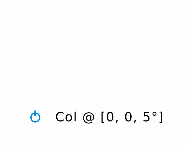
Step 1: We determine the starting point of the zone based on its anchor attribute.
In this case, only a 5° rotation was specified, so our initial mark is at [0, 0, 5°].
This blue point is going to be our running "column anchor", where each column will start building from.
Since spread doesn't apply to the first column of any zone, and there's no stagger or splay given, we can start iterating over the zone's columns.

Step 2: To start actually laying out the first ("pinky") column, we copy the current column anchor to a running "row anchor" (marked red).
Note that this is where key-level orient/shift/rotate would take effect, if any were specified.

Step 3: When a row anchor is finalized, a key is laid out there – shown here by 18mm by 18mm squares, representing regular keycaps. It's worth emphasizing that the keys we're generating here are always defined as the middle points of these visualization squares. They're not the squares themselves, as we don't always necessarily want to put rectangles at these locations.
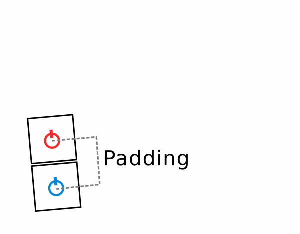
Step 4: Now that the first key of the column is fixed, we add padding to figure out where the next row should go.
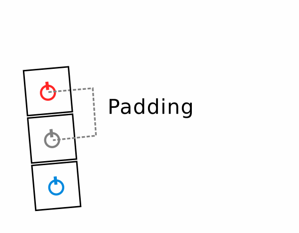
Step 5: And we keep doing this until we run out of rows in the current column – cumulatively, always adding padding (and potential orient/shift/rotate modifiers) to get to the next location.
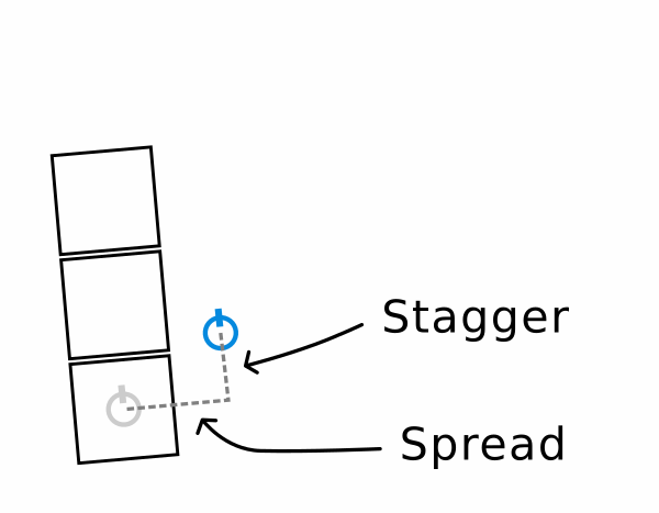
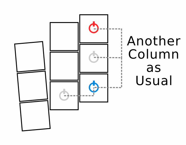
Step 6: Once the current column is done, we move on to the next column by applying spread (to move horizontally) and stagger (to move vertically).
Note that the column anchor is still "skewed" at the original 5° rotation.
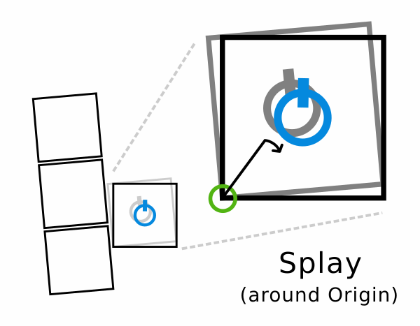
Step 7: After spreading and staggering, inter-column splay is applied – again, cumulatively.
By default, splaying happens "around" the point itself, so it doesn't affect its x/y position, only its rotation.
But we can change this with an optional origin to rotate around.
In this case, it's used so that the column hinges around the first key's bottom left corner (so that the rotation doesn't accidentally make that exact corner overlap the first column, as it would during sufficient rotation around the key's center).
Note that this splay takes us back to 0° (upright) rotation.
Step 8: From this new column anchor, we can repeat the same in-column process we saw before: copy it to a running row anchor, and create the column's relevant rows one by one, leaving padding in between stops.
Step 9: And now steps 6-7-8, again.
We create the new column anchor by spreading/staggering/splaying the old one, and lay out the next column, row by row.
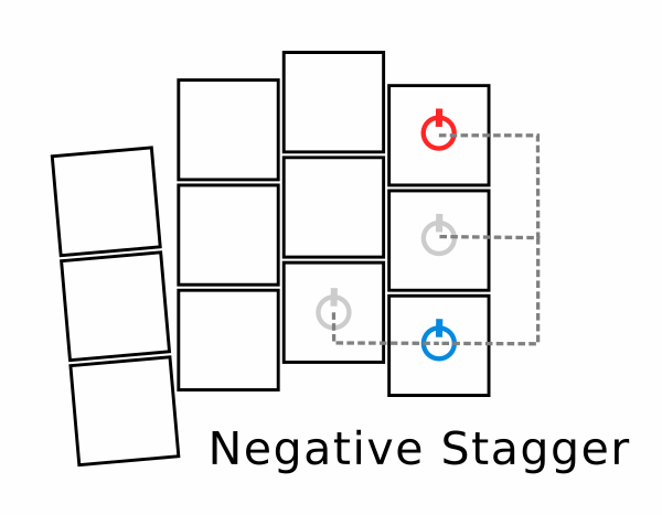
Step 10: Same old, same old, only now the stagger value is negative.
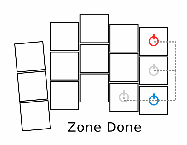
Step 11: Once more for the inner column, and we're done with this zone.
Once we have an existing zone (matrix), we can anchor further zones to it – like, say, a thumbfan.
- Config
- 1
Step 1:
Examples#
Choc spacing
arst neio
- Config
- Visualization
Row overrides
arst neio
- Config
- Visualization
Column arcs
arst neio
- Config
- Visualization
Adjustments#
Once we're done with zone-specific definitions, we can adjust the individual zones as a whole, or even all the zones collectively. The corresponding config sections look something like this:
points: zones: zone_name: rotate: <number> # zone-level rotation mirror: <axis> # zone-level mirror rotate: <number> # global rotation mirror: <axis> # global mirrorRotation#
In this context, rotate can apply an angle to all relevant points, most often used to simulate the inter-half angle of one-piece boards.
If specified at the zone level, it applies to the points of that zone only – if specified globally, it applies to all points.
The origin of the rotation is always assumed to be [0, 0].
This doesn't matter for global rotations, but should be considered for zone-level ones.
Mirroring#
At this stage, all "original" points are declared and positioned. And since the default direction in Ergogen is left-to-right, this usually means the left side of the board. But there's usually two sides to a board, so to save us the work of replicating everything on the right, Ergogen offers a way to mirror "source" points automatically along an axis.
If the mirror field is a number, it will be used as the x coordinate of the axis to mirror along.
Otherwise, it's going to be treated as an anchor with an additional distance field, where the anchor defines an arbitrary reference point and distance defines how far away it should be from its eventual mirror image.
As with rotation, mirroring can be applied to individual zones, or all of them simultaneously at the end, depending on which of the above two mirror declarations we use.
caution
The mirror field can have different meanings depending on its location in the config.
As we just saw, points.mirror and points.zones.<zone_name>.mirror are for declaring what points should be mirrored to the other side and along what axis.
These are not to be confused with the key-level mirror attribute (appearing at any of the 6 levels we've discussed for inheritance), which provides a way to override any other key-level attribute for mirrored versions of points.
Now if our design is symmetric, we're done.
Otherwise, we need to use the asym key-level attribute to indicate which side any given point should appear on.
If it's set as source, mirroring will simply skip this key, as it should only be present on the source side, as it was declared.
If the asym field is set as clone, mirroring will "move" the point instead of copying it, because it should only appear on the mirrored side.
The default value of both assumes symmetry – so the given point should appear on both sides of the board.
tip
The source/clone pair was chosen to replace the old left/right as the canonical options for the asym field so as not to make any hardcoded assumptions about the spatial relationships between original and mirrored positions.
But as aliases, origin/image, base/derived, primary/seconday and even the old left/right pairs are also supported, so feel free to use whichever makes most sense to you.
And this concludes point definitions. This should be generic enough to describe any ergo layout, yet hopefully easy enough so that you'll appreciate not having to work in raw CAD.
Examples#
Zone-level adjustment
arst neio
- Config
- Visualization
Post-adjustment zones
arst neio
- Config
- Visualization
Asymmetry
arst neio
- don't forget a key-level mirror example here, too
- Config
- Visualization